

Introduction: The Challenge of Non-Standard Industrial Filtration
In modern industrial processing—from harsh petrochemical refinement to ultra-clean pharmaceutical steam filtration—off-the-shelf polymer cartridges frequently fail to withstand extreme temperatures, differential pressures, or aggressivechemical attack. When standard catalog items cannot meet specialized housing dimensions, connection types, ormicron retention curves, custom-engineered metal filter elements become the only viable engineering solution.
Whether you have a fully specified 3D CAD model, a legacy 2D manufacturing blueprint, or a worn physical sampleextracted from an imported machine with zero technical documentation, professional metal filter manufacturers can bridge the gap from concept to high-volume production.
Step 1: Engineering Assessment & Feasibility Analysis
A reliable custom manufacturing workflow begins with a thorough evaluation of the operating environment and physical requirements. When reviewing customer-supplied technical data, engineers evaluate
- Operating Parameters: Max operating temperature, continuous pressure, differential collapse pressure (ΔP), and flow rate velocity
- Process Fluid Compatibility: Acidity (pH range), caustic concentrations, steam sterilization cycles, and particle abrasiveness.
- Filtration Efficiency & Pore Rating:Nominal vs. absolute micron ratings (from 0.2 µm up to 500+ µm).
- Mechanical Constraints: End fitting configurations (Threaded, Flanged, NPT/BSPT, 222/226 O-ring, Tie-rod, or custom Bayonet locks).
Step 2: Manufacturing from CAD Drawings vs. Physical Samples
| Input Method | Required Information / Process | Key Verification Steps | Lead Time for Prototyping |
| Engineering Drawings (CAD /STEP / DWG) | Tolerances, alloy grade (304, 316L, Hastelloy), micron rating, pleat count, and end cap specifications. | DFM (Design for Manufacturability) review, welding seam analysis, pore integrity calculation. | 5 – 10 Business Days |
| Input Method | Required Information / Process | Key Verification Steps | Lead Time for Prototyping |
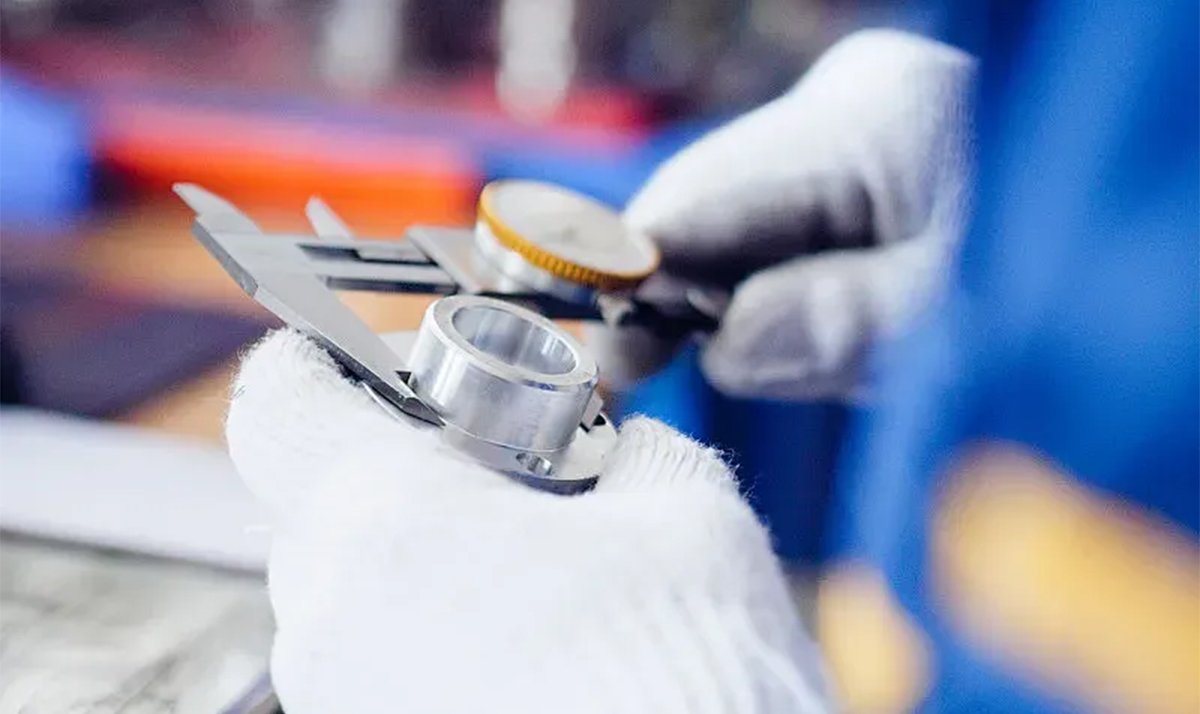
| Physical Sample / Worn Part | Dimensional measurement (CMM), alloy spectrometer test, weave pattern analysis, air-flow porosity test. | Reverse engineering 2D/3D modeling, micron rating estimation via bubble point benchmarking. | 7 – 14 Business Days |
Step 3: Core Manufacturing Processes
Depending on structural stiffness and filtration accuracy requirements, three primary metallurgical processes are deployed:
- Multi-Layer Sintering: Diffusion bonding under high-vacuum furnaces (up to 1250°C) without chemical binders,fusing woven wire meshes into a unified, non-migrating matrix.
- Porous Sintered Metal Powder: Iso-statically pressed spherical or irregular alloy powders for precise deep-bed filtration in liquid and gas streams.
- Pleating & Precision TIG/Laser Welding: Precision mechanical pleating to expand effective filtration area by 200%–500%, joined via longitudinal automated laser welds to eliminate bypass leaks.
Step 4: Quality Verification & Delivery
Every custom batch undergoes non-destructive and destructive QA validation: ISO 2942 Bubble Point Integrity Testing, collapse pressure testing, and surface passivation (pickling or electropolishing) to ensure immediate deployment in your production line.
Have a Custom Filter Drawing or Worn Sample?